Recovered energy funding corporation
Renewable energy opportunities
RECOVERED ENERGY FUNDING CORPORATION
A PROCESS FOR RECYCLING WASTE THROUGH PLASMA GASIFICATION AND CONVERTING IT INTO ENERGY AND OTHER VALUABLE PRODUCTS
BUSINESS PLAN FOR MUNICIPALITY OF __________________________
Project Team
This environmentally vital project takes full advantage of the latest technologies as a means for converting solid waste into energy and income, and will be carried out by some of the major US and Canadian companies in the field.
RECOVERED ENERGY FUNDING CORPORATION
TABLE OF CONTENTS
Table Of Contents 1
1 Executive Summary 1
1.1 Project Description 1
1.2 Project Owner/Management 1
1.3 License 1
1.4 Project Cost 1
1.5 Project Funding 1
1.6 Phased Construction 1
1.7 Products Produced 1
1.8 Project Requirements 1
1.9 Sources Of Revenue 1
1.10 Environmental Impact 1
1.11 Financial Summary 1
1.12 Use Of The Cash Surplus 1
1.13 Benefits Of The Project 1
1.14 Disclaimer 1
2 The Project 1
2.1 Project Description 1
2.2 Requirements Of Each Participant 1
2.3 Project Purposes 1
2.4 Project Schedule 1
3 Project Cost/Funding 1
4 Sources Of Revenue/Fee Structure 1
5 Transaction Structure And Project Team 1
5.1 Transaction Structure 1
5.2 Project Team 1
5.3 Plant Operations 1
6 Market Analysis 1
6.1 Landfills 1
6.2 Power Plants 1
6.3 Greenhouse Gas Emissions 1
6.4 Disaster Security 1
6.5 Pure Water 1
6.6 Processes For Handling Waste 1
7 Analysis Of The Technology 1
7.1 Plasma Gasification 1
7.2 Power Plant 1
7.3 Other Equipment 1
Plant Operations 1
8 Financial Projections 1
9 Risk Analysis 1
10.1 Political Risk 1
10.2 Social Issues 1
10.3 Technical Risks 1
Exhibit 1 1
Exhibit 2 1
1 Executive summary
Recovered Energy, Inc. (REI) is a project development, engineering and construction management company that has designed a system for converting any type of waste into electricity and other usable products with a 99.9% conversion rate and virtually no residuals. The Recovered Energy System™ offers the first real long-term solution for the disposal of all types of waste.
Recovered Energy Funding Corporation (REFCO) is a Company that funds as well as constructs Waste Energy Recovery Plants using the REI Technology in a number of contractually designated territories throughout the world.
The objective of this Business Plan is to provide a comprehensive, financially attractive solution to long term waste disposal issues facing the Municipality of with a positive environmental impact in a format that is economically viable for the long-term and provides meaningful humanitarian benefits to the community for the life of the project.
1.1 Project description
REFCO proposes to supply an Integrated Plasma Gasification Combined Cycle (IPGCC) Plant to the Municipality of , capable of processing a variety of waste streams and producing electricity, glass and other valuable products. Optionally, the Plant can be configured to produce pure distilled water from steam or the glass can be converted into ceramic products. The implementation of some of the options will depend on the available funding. The Power Plant can be either a 50 cycle turbine (Option A) or a 60 cycle turbine (Option B):
Units Option A Option B
Waste processing capacity tons/day 2,500 2,500
Power produced from the waste (A) mWh 73-105 73-105
Power produced from fossil fuel mWh 75-147 110-177
Total power produced (B) mWh 180-220 215-250
Distilled water capacity (D) m3/day 30,000 30,000
Ceramic capacity (E) tons/day 400 400
Employees required (C) each 280-320 280-320
The power produced from the waste will vary depending on the moisture content and characterization of the waste. The waste does not necessarily utilize all the turbine capacity. The difference between the total power produced and the power produced from waste comes from a fossil fuel such as natural gas or diesel fuel.
- The total power produced is the total net power after deducting the Plant’s internal load, adjusted for altitude. Option A is a 50 cycle turbine and Option B is a 60 cycle turbine.
- The exact number of employees will depend on productivity, employment philosophy, wage rates and other factors.
- The distilled water is the maximum size of Plant that is offered. The actual size of unit used will depend on the need for water, the budget available and other factors.
- The ceramic capacity is the maximum offered capacity for the Ceramic Plant. The actual size of the Plant will depend on the budget available and other factors.
1.2 Project owner/management
The Funding Program offered in this Business Plan requires that the physical title to the Plant facility be held by Recovered Energy Funding Corporation. A separate entity will be selected (which can be the City, Municipality, a Company owned by the Municipality, a private company or a publicly held company) to manage the business. REFCO, the Municipality of and the operating entity will share in the profits. An option can be granted for a transfer of ownership in the future under specific conditions, if so desired by the Municipality.
1.3 License
REFCO is required to purchase a license from REI. The licence can either be a Site License that covers a specific location and project or it can be a Territory License that covers an unlimited number of Plants within a defined Territory.
1.4 Project cost
The Project cost is $1.5 Billion USD for either Option A or Option B. This is the maximum amount of funding that is available under this Business Plan. The number of features that are available will vary from Plant to Plant.
1.5 Project funding
The entire Project Funding (hard costs and soft costs) is arranged by REFCO at no cost to the Municipality.
1.6 PHASED CONSTRUCTION
The Project will be completed in two phases. Phase I includes the Power Plant, Water Distillation System (if included), office building and engineering for Phase II. The Power Plant and Water Distillation Plant will be operational in 22-26 months and the Power Plant will begin producing electricity using a fossil fuel (preferably natural gas). Phase II takes place concurrently with Phase I but requires more time to complete. Phase II includes the balance of Plant and will be operational about 6-12 months after Phase I is complete. Once Phase II is complete the Power Plant will switch from operating on fossil fuel to operating on a combination of synfuel from the waste and fossil fuel. This approach allows the Plant to begin generating revenues as quickly as possible.
1.7 Products produced
- The Plant can be configured to produce the following products. The final selection of products produced will vary slightly depending on the Plant location, the needs of the community and the options selected:
- Between 800 kW to 1,200 kW of electricity for every ton of waste processed, depending on the moisture content of the waste, type of waste and other factors. The total nameplate capacity of the Power Plant will be between 180 to 250 mWh, depending on whether it is a 50 cycle or 60 cycle turbine, the altitude, the turbine supplier, and other factors. The turbine will first be used to produce power from the synfuel produced from the waste. Whatever capacity is remaining will be used to produce power from natural gas or diesel fuel.
- Vitrified glass equal to the inorganic content of the waste, which can range from 10% to 25%. The glass can be used to produce various building materials, such as building blocks, decorative pavers, roof tiles, floor tiles or concrete aggregate. The glass can also be used to produce a variety of ceramic products.
- Up to 2,900 gallons (11.1 cubic meters) of purified, distilled water for every megawatt of electricity produced. Low pressure steam from the process is used to distill an independent source of water. The Water Distillation Plant is tied to the Power Plant, not the gasification plant and the water produced has no interrelation with the waste.
- Recycled metal, hydrochloric acid and several options of sulfur products.
1.8 Project requirements
- Contracts for the supply of waste, purchase of electricity and purchase of water (if the water option is selected).
- Raw water of almost any quality for the distillation unit equal to approximately five to eight times the amount of distilled water produced (if the water option is selected). Good quality water is needed for cooling tower and boiler blow down if the distilled water option is not selected.
- Natural gas and/or diesel fuel (as per spec) for the Power Plant to utilize the excess power capacity.
- Land—approximately 35 ha (80 acres). This is the amount of land we would like to have, allowing for expansion and room for some of the other features. The Plant can fit on less land if the land is not readily available.
- Raw materials—coke (3-5% of waste input), silica (2-4% of waste input), sodium hydroxide (varies based on desired sulfur products produced) and miscellaneous water treatment chemicals.
- Financing requirements as described in more detail in Section 6 of this Business Plan.
1.9 Sources of revenue
The Licensee will receive the following fees from the Municipality or its separate contracting agency:
- A tipping fee for each ton of waste that is delivered to the Plant. There will be a basic rate for municipal waste and yard waste. Other types of waste may carry higher fees.
- A fee for the electricity.
- A fee for the distilled water (if applicable).
- The glass or ceramic products will be sold based on market value.
- Section 4 of the Business Plan includes a table that shows various combinations of fees.
1.10 Environmental impact
- The Project will have a positive impact on the environment.
- The Project eliminates the need for a landfill for the waste that is processed in the facility.
- The emissions from the Plant are significantly below EPA standards.
- The electricity produced from synfuel does not release new or additional greenhouse gases into the environment or damage natural fishing and wildlife habitats as fossil fuel and hydro power plants do.
- The Plant is capable of processing all types of waste including hazardous waste, medical waste, PCB’s and other types of waste that are damaging to the environment.
- The Plant is clean and aesthetic, eliminates the odor from the waste, eliminates unsightly landfills, does not reduce the value of the surrounding land and makes land available for more productive use.
1.11 Financial summary
The Plant will generate an annual profit subject to agreed pricing and volumes. Based on the pricing table shown in Section 4, the annual operating income is projected to be in excess of $40 Million USD. The actual operating profit may vary depending on wage rates, construction costs, raw material costs and other factors.
1.12 USE OF THE cash surplus
The portion of the operating profits belonging to the Municipality can be used by the Municipality in any way it wishes to. One half (50%) of the operating profits belonging to the Recovered Energy Funding Corporation will be used for humanitarian purposes within the general community to fund community projects such as schools, hospitals or low-income housing.
1.13 BENEFITS OF THE PROJECT
- Extremely beneficial source of project financing
- Long-term source of revenue for humanitarian projects
- Solution to waste problem
- Creation of good secure jobs
- Development of a new industry
- Reduced burden on landfills and reduction of the hazards of landfills
- Improved environment
This Business Plan will provide a unique and rare opportunity for the Municipality to be on the leading edge of technology in a way that removes the technology, political and financial risks typically associated with projects of this nature.
1.14 Disclaimer
This Business Plan is based on an estimate of capital cost that could vary from location to location. The capital cost was derived based on average costs using non-union labor. The actual capital cost will be higher or lower depending on the location. The options available, capacity of the Plant and fees needed may vary from location to location. The figures in this Business Plan are intended only as a guideline. A study will have to be made for the Municipality of to determine the final Business Plan for that location.
2 The project
2.1 Project description
REFCO proposes to supply an Integrated Plasma Gasification Combined Cycle (IPGCC) facility capable of processing a variety of waste streams and producing electricity, purified water, vitrified glass, hydrochloric acid, various sulfur products and recycled metal. An option for ethanol is in the development stage and will be available in the future. A simplified process flow drawing is shown below:
The Power Plant can use GE, Siemens-Westinghouse or Alstom turbines, although REI has a preference for the GE turbine. The specific turbine will depend on whether the power needs to be 50 cycle (Option A) or 60 cycle (Option B) and on which supplier is selected. All of the turbines are in a similar size range. Each of the turbine options has experience operating on the fuel mixture that will be provided.
The waste processing capacity is 2,500-3,000 tons per day of typical municipal solid waste. Other types of waste will have different capacities, depending on the BTU value of the waste. The Power Plant is designed to run at full rates using a combination of the synfuel produced from the waste and natural gas. The turbines all have more capacity than the synfuel from the waste will handle. The fuel source for the excess turbine capacity must come from natural gas or other fossil fuel. The excess turbine capacity allows for expansion of the waste processing capacity without expanding the Power Plant.
The Plant can be designed to produce distilled water using the waste steam from the process. The steam turbine in the Power Plant produces electricity from steam. Once the energy has been taken out of the steam what is left is very low pressure steam. This low pressure waste steam must be condensed. Traditionally a cooling tower is used to condense the steam. However, this steam still has value. A multi-effect distillation unit can be installed which will distill an independent source of raw water using this waste steam. In the process of distilling the water the steam is condensed, thereby eliminating the need for a cooling tower. The result is that the Power Plant can be used to produce pure water instead of using water for condensing. The source water can be sea water, lake water, canal water, river water or other sources of water. The quality of the water can be relatively low. This portion of the Plant is optional, depending on the need of the community for water and the capital funding available.
The inorganic material in the waste (soil, silica, glass, concrete, rocks, dirt, etc.) is converted into vitrified glass. The glass can be further processed into a number of products, including high quality ceramic products through an annealing oven process. The ability to include a Glass Processing Plant in this proposal will depend on the actual capital cost and other options selected.
REFCO proposes to supply to the Municipality of an Integrated Plasma Gasification Combined Cycle Plant (IPGCC) facility capable of processing a variety of waste streams and producing electricity, glass and other valuable products. Optionally, the Plant can be configured to produce pure distilled water from steam or the glass can be converted into ceramic products. The implementation of some of the options will depend on the available funding. The Power Plant can be either a 50-cycle turbine (Option A) or a 60-cycle turbine (Option B):
Units Option A Option B
Waste processing capacity tons/day 2,500 2,500
Power produced from the waste (A) mWh 73-105 73-105
Power produced from fossil fuel mWh 75-147 110-177
Total power produced (B) mWh 180-220 215-250
Distilled water capacity (D) m3/day 30,000 30,000
Ceramic capacity (E) tons/day 400 400
Employees required (C) each 280-320 280-320
- The power produced from the waste will vary depending on the moisture content and characterization of the waste. The waste does not necessarily utilize all the turbine capacity. The difference between the total power produced and the power produced from waste comes from a fossil fuel such as natural gas or diesel fuel.
- The total power produced is the total net power after deducting the Plant’s internal load, adjusted for altitude. Option A is a 50-cycle turbine and Option B is a 60-cycle turbine.
- The exact number of employees will depend on productivity, employment philosophy, wage rates and other factors.
- The distilled water is the maximum size of Plant that is offered. The actual size of unit used will depend on the need for water, the budget available and other factors.
- The ceramic capacity is the maximum offered capacity for the Ceramic Plant. The actual size of the Plant will depend on the budget available and other factors.
A rendering of what the entire facility is intended to look like is shown below:
2.2 Requirements of each participant
The requirement of each of the participants is as follows:
The Municipality of :
- The Municipality of will donate approximately 35 hectares (80 acres or 320,000 m2) of land to REFCO for the Plant site. The Project can fit on less land depending on the shape, road access and other factors.
- The Municipality of will either enter into a contract with the Recycling Plant for the purchase of the electricity or will cause another company to enter into a purchase contract. The term of the purchase agreement shall not be less than 25 years.
- The Municipality of will enter into a contract with Licensee to supply an average of 2,500 tons of municipal waste (or BTU equivalent) per day with options for increased volume as the demand increases. (Tons are defined as short tons of 2,000 pounds.)
- Assuming the water option is selected; Municipality will either enter into a contract with Licensee for the purchase of the distilled water or will cause another company to enter into a purchase contract. The term of the purchase agreement shall not be less than 25 years.
- The Municipality of will provide raw water or will cause another company to provide raw water in mutually agreed quantity and quality for cooling.(Sea water can be used as a coolant as long as a Desalinization Plant is included in the project configuration)
- The initial prices and fees will be consistent with the chart shown in Section 4; however, the actual numbers may vary based on a variety of factors. The final prices will be negotiated once the specific parameters can be established. REFCO will make every effort to ensure that the fee structure recommended will be acceptable to the Municipality of and will not disrupt existing fee structures for infrastructure services.
- The Municipality of will not be asked to provide any of the funding for the Project.
Recovered Energy Funding Corporation (REFCO):
- The Plant and equipment will be owned by REFCO.
- REFCO will appoint a qualified third party for the daily operation of the company.
- A portion of REFCO’s share of the profits from the Plant will be used to support programs, projects and activities for the general benefit of the community, as approved by a Board of Trustees that will include REFCO representatives and members of the local community. The potential projects can be submitted either by the Municipality or by organizations within the community that have worthy projects.
- The Plant can be a Joint Venture with a local entity if the Municipality or Country wishes. The details would be agreed to during the Plant Construction Phase.
Recovered Energy, Inc. (REI) and it Partners:
- REI will provide the process engineering for the Plant and will coordinate with the detail engineering company.
- REI will provide engineering, procurement and construction services through its Technical Partners. Together with its subcontractors, suppliers and engineering and construction team REI will provide the following basic facility:
- Plasma Gasification System to process municipal waste or the equivalent BTU value of other waste.
- Front End Material Handling System and Feed System for the plasma gasifiers
- Heat Recovery System
- Pollution control equipment
- Cooling towers
- Water Treatment System
- Filter Systems
- Cooling Systems for the torches, gasifier and Glass Quench Systems
- HCL Distillation System
- Electrical Power Generation Plant
- HRSG system to generate electricity from the steam both from the heat from the gasifier and from the gas turbine
- Substation, transformer, switchgear and connection to the grid at the battery limits
- Steam Condenser and Boiler Feedwater System
- Pumps, blowers, miscellaneous equipment
- Storage for coke, silica, caustic soda, liquid waste, vitrified glass, HCL, sodium bisulfite, fire water and water treatment chemicals.
- Raw Material and Finished Goods Handling and Loading System
- Process and detail engineering
- Permit applications
- Process plant and maintenance buildings, office building
- Civil works within battery limits, including site utilities, fire water system, roads, site preparation, fencing and landscaping within battery limits
- Installation of the Plant
- Freight
- Spare parts
- Rolling stock, loaders, forklifts
- Initial training of operators
- Startup services
- Several features are available depending on the availability of funds, actual construction costs and other factors. The budget will not include all of these features so a selection process will take place during the Feasibility Study. These features include, but are not limited to the following.
- Expanded waste processing capacity to 3,000 tons per day.
- Transfer station(s)
- Power line
- Natural gas line
- Glass Block Plant
- Glass Ceramic Plant
- Multi-effect Distillation System
- Rail spurs
- Road infrastructure to accommodate the Plant
2.3 Project purposes
The Project being proposed by REFCO has a six-fold purpose:
1-Management of waste
2-Production of green electricity
3-Production of purified water
4-Production of building materials from vitrified glass
5-Protection of the environment
6-Funding of humanitarian projects,
such as schools and hospitals.
2.3.1 Waste Management
Waste collection, transport and disposal into a landfill are not waste management. Managing waste is the collection and ultimate disposal of the waste without causing environmental damage. Every city in the world accumulates significant waste and has to deal with the problem of how to dispose of it. The amount of municipal waste generated per person can vary from 2 pounds per day per person up to 5 pounds per day per person, depending on the country and level of affluence. This amount does not include hazardous waste, industrial waste and other types of waste that are not included in the definition of municipal waste.
REFCO believes that waste should be managed and treated as a resource—not a liability. REFCO believes that waste can be processed in an environmentally friendly manner that will eliminate the need for landfills in the future and that valuable products can be recovered from the waste. In order to accomplish this goal REFCO will implement the Recovered Energy System™, which converts virtually any type of waste into electricity, building materials and other valuable products.
Most cities in the world with populations of 1,000,000 to 1,500,000 people can support a Recovered Energy System™ and would potentially qualify for this offer.
2.3.2 Green Electricity
The supply of adequate electricity to its community and to its industries is a major challenge for most communities throughout the world. The demand for electricity continues to grow but the supply is not as easily expanded. As a society we pay a significant environmental price for the production of electricity from most conventional sources of power. Hydropower is the most economical form of power but our rivers can only hold so many dams. Hydropower is severely impacted by the amount of rainfall. Nuclear Power Plants are environmentally not safe because of the potential impact of a failure. In addition, disposing of spent fuel has become a crisis in many countries. Traditional Coal Plants are the cause of “acid rain” and are primary contributors to the greenhouse effect. The newer version of Coal Gasification Plants called IGCC Plants, have fewer emissions than traditional Coal Plants and have a higher efficiency, but they still contribute heavily to the greenhouse effect. Natural Gas Plants have become quite popular for demand power because they are easy to startup and shut down. They are fairly clean but they contribute to the greenhouse effect and natural gas has a limited supply. Solar power and wind power are not practical in most areas and have a limited capacity based on current technology. Fuel cells represent a significant potential, however, they are still in the development stage.
Green electricity is defined as power produced from renewable resources. Renewable resources include wind, solar, hydro and waste. REFCO believes that municipal waste and other forms of waste represent a valuable resource and source of green electricity that should be exploited. Energy produced from waste has the following advantages over any other form of renewable energy.
- Municipal waste will always exist in the locations where the power is needed the most.
- The use of waste to produce power using the Recovered Energy System™ will always have less environmental impact than any other alternative use for or disposal of the waste.
- Municipal waste can provide up to 1/3 of our total power requirements and it is readily available.
- There is a raw material cost to most other forms of energy, whereas waste is able to charge a tipping fee.
- Mismanagement of waste will cause serious long-term environmental damage.
- Converting municipal waste into electricity does not contribute to the greenhouse effect and when properly done has a positive environmental impact.
2.3.3 Purified Water
Water is the most valuable natural resource that exists. Without water life does not exist. Fresh water makes up a very small portion of our total water supply. Eighteen percent (18%) of the world does not have any form of improved water supply. Much of the other 82% do not meet current EPA clean water drinking standards. As a consequence, 2.2 million people in developing countries, mostly children, die every year from diseases associated with lack of safe drinking water and inadequate sanitation. Traditional sources of spring or well water are becoming contaminated and the overall quality of water has deteriorated. The demand for some form of treatment of the water is increasing steadily. Every community in the world is faced with increasing demands on municipal potable water treatment systems and could use better water. Bottled water has become a major industry over the past decade in every city in the world because people want better quality water and do not trust the municipal treatment plants.
The Recovered Energy System™ produces a significant amount of steam. Once the energy has been removed from the steam it must be condensed and the condensate is then reused to make more steam. Traditionally, large cooling towers are used to condense the steam. These cooling towers require large amounts of fresh water for makeup water to replace the water that was evaporated. The Plant does not use cooling towers. Instead a multi-effect distillation (MED) system is used to condense the steam. At the same time the MED unit is condensing the steam it is also distilling an independent source of water. Seawater, river water, lake water, canal water or well water is pumped into the MED unit. The use of vacuum systems allow the low-pressure waste steam (steam that is at .34 bara) to distill 50% of the source water. The end result is that waste steam from the process is used to produce pure water and at the same time the water is used to condense the steam from the Power plant. The Plant will produce as much as 30,000 cubic meters (7,900,000 gallons) of pure distilled water per day at sea level and full power production. The flow of raw source water to support this output is 60,000 cubic meters based on using salt water at 3.6% salinity. If fresh water is used the amount of source water required is less. An additional 240,000 cubic meters of source water is used to condense and cool the final product. In total, 300,000 cubic meters of raw source water is pumped into the Plant, of which 30,000 cubic meters comes out as pure distilled water with a total dissolved solids (TDS) of 10-20 ppm. The other 270,000 cubic meters comes back to the source 6 degrees C warmer and slightly higher salinity. The pure distilled water produced can then be injected into the city water supply to supplement and improve the existing potable water supply. Alternatively, electrolytes can be added to the distilled water and be treated with ozone to produce purified water that meets bottled drinking water standards and can be sold as purified bottled water.
The offer contained in this Business Plan is based on selling the water to the Municipality as potable water at a price that is reasonably comparable to the current international cost for treating water. The highest value for the water would be to add electrolytes and then to sell the water as purified drinking water (bottled water). Currently bottled water (PET bottles) sells for as much as $1 per liter in stores almost anywhere in the world. Most of this cost is for the containers, distribution and marketing. At this price most people cannot afford to drink bottled water. The Recovered Energy System™ will allow for the production and distribution of purified drinking water in refillable 20 liter bottles at very low prices that would be affordable to most people. This would not replace the existing market of people who want the PET bottles for specific events or for convenience. By selling drinking water, the Plant would increase its profitability allowing the Owner to fund more humanitarian projects for the community.

2.3.1 Vitrified Glass
The Recovered Energy System™ operates at very high temperatures. The melt zone of the gasifier can be 5000 to 8000°F. At the temperatures used all inorganic material, including dirt, rocks, gravel, sand, concrete, gypsum, glass, etc. is vitrified into a glass material that looks like obsidian. The glass flows out of the gasifier into a quench tank, in which case the glass is immediately shattered into small pellet size granules. Alternatively, the glass can be tapped out of the gasifier into a ladle and poured into a mold. The glass has several uses and values as described below:
- Assuming the glass is quenched, the lowest value use for the glass is for road base material or aggregate for concrete or asphalt. The value of aggregate glass is $1 to $10 per ton.
- Assuming the glass is quenched, the next highest value is to mix the glass aggregate with Portland cement and press the aggregate into blocks, using a standard block plant. The blocks can be used as paving stones, decorative blocks or landscaping blocks. Structural blocks cannot use more than 25% glass in the aggregate mix. Most of the incinerators in Japan have installed plasma units on the back end of their plant to vitrify the incinerator ash into glass. Japan has developed a broad base market for the glass products that are produced from the glass. The value of the blocks can be up to $100 per ton. The blocks provide more jobs and a value added building material from the glass.
- If the glass is tapped from the gasifier into a ladle, the glass can then be poured into a mold. The glass would then go to an annealing oven where the temperature is properly controlled to convert the glass into ceramic. The ceramic can be glazed to produce different colors and designs. The glass ceramic is structurally stronger than marble or granite and can be used in a wide variety of applications including, but not limited to, ceramic tiles, countertops to replace Corian or stone, fascia panels for buildings to replace granite and marble, flooring panels to replace marble or granite, tombstones, formed panels for highway sound barriers to replace concrete panels, highway dividers to replace concrete dividers, telescope lenses, industrial wear plates, high temperature ceramic tiles for industrial applications, large blocks to be used for ports either in piers or to line the channel, etc. The potential applications are limitless. The value of some of these ceramic products can be as much as $1,000 per ton.
This Business Plan can include a Block Plant or a Ceramic Plant depending on which features are taken, the actual capital cost as adjusted for the specific site and the amount of budget that is available.
2.3.2 Protection of the Environment
The Recovered Energy System™ protects the environment in a number of ways:
- The project eliminates the need for a landfill for the waste that is processed in the facility
- The emissions from the Plant are significantly below EPA standards.
- The electricity produced does not release new greenhouse gases into the environment or damage natural fishing and wildlife habitats as Fossil Fuel and Hydro Power Plants do.
- The Plant processes all types of waste including hazardous waste, medical waste, PCB’s and other types of waste that are damaging to the environment if untreated. The Recovered Energy System™ does not have the long-term environmental effects compared to conventional methods when disposing hazardous waste.
- The Plant is clean, aesthetic, eliminates the odor from the waste and eliminates unsightly landfills.
2.3.3 Humanitarian Benefit
One of REFCO’s primary objectives is to provide funding for humanitarian projects in the community. A significant portion of REFCO’s share of the income will be used to fund humanitarian projects that include schools, hospitals, low-income housing or expansion of the Plant. The specific projects that are funded will be approved by the Board of Directors of REFCO which will include representatives from the local community and government.
2.4 Project Schedule
The Project will be completed in two phases. Phase I includes the Power Plant, Water Distillation System, office building and engineering for Phase II. The Power Plant and Water Distillation Plant will be operational in 22-26 months and the Power Plant will begin producing power from fossil fuel. Phase II takes place concurrently with Phase I but requires more time to complete. Phase II includes the balance of Plant and will be operational about 6-12 months after Phase I is complete. Once Phase II is complete the Power Plant will switch from operating on fossil fuel to operating on a combination of synfuel from the waste and fossil fuel. This approach allows the Plant to begin generating revenues as quickly as possible.
3 Project cost/funding
The Project Funding is $1 Billion USD for either Option A or B because that is the maximum amount of funding available. The actual cost of each option is obviously different because the Power Plant is not the same size for each option. The Project cost includes the initial construction/equipment cost, employee training, construction period interest; contingency, spare parts and all loan and guarantee fees. There are several features that are available such as the Distilled Water Plant, the Glass Block Plant, the Ceramic Plant, transfer station(s) or tie-ins to gas lines or the grid. The options that are selected will depend on the specific project conditions and objectives and the budget that is available.
The Project Funding for 100% of the project cost will be arranged by REFCO. Working capital for the operation of the Plant will be borrowed by the Operator. The Municipality of
is not required to provide any of the funding for the Project or the operation of the Plant, other than the cost of the land.
4 Sources of revenue/fee structure
The Project will receive the following fees from the Municipality or its separate contracting authority:
- A tipping fee for each ton of waste that is delivered to the Plant. There will be a basic rate for municipal waste and yard waste. Other types of waste may carry higher fees.
- A fee for the electricity.
- A fee for the distilled water.
- There is a direct correlation between the price of electricity and the tipping fee. These are the primary economic drivers. REFCO tries to achieve an overall economic profit margin. It doesn’t matter whether the economics come from the waste or the power or a combination of the two. In some situations the value of power will be high and the tipping fees will be low or visa versa. That is fine as long as the overall combination of the two meets the economic requirements of the Project. When tipping fees are high they are subsidizing the price of electricity. When electricity is high it is subsidizing the tipping fee. The following table shows the relationship of the various rates and typical rates that would be charged for various scenarios. Each specific condition will be different depending on labor rates, capital cost, raw material cost, other types of waste that are available, altitude and a variety of other factors. This table is intended only as a guideline. REI will work with each specific situation to adjust the various rates to find the right combination.
Fee Table
Price for Price for Option A Option B
Electricity Electricity Tipping Fee Tipping Fee Price for
From SG (A) From NG (B) Charged (C) Charged (C) Water (D)
(US $) (US $) (US $) (US $) (US $)
25 39 72 71 .80
30 43 66 65 .80
35 47 60 59 .80
40 51 54 53 .80
45 55 48 47 .80
50 59 42 41 .80
55 63 36 35 .80
60 67 30 29 .80
65 71 24 23 .80
70 75 18 17 .80
- This is the price charged for each megawatt of electricity produced from the syngas.
- This is the price charged for each megawatt of electricity produced from natural gas. This price is determined by multiplying the heat rate of the turbine times the cost of gas plus a factor for operations and maintenance of the Plant and plus a factor for fixed costs. For example, the prices shown in this table assume the heat rate is 7000 and the cost of fuel is $5 per million BTU. The total cost of power is $35 per mWh for fuel cost plus O&M cost, plus fixed cost.
- The tipping fee is the price charged for a short ton (2,000 pounds) of municipal waste or yard waste. Other types of waste will have different tipping fees and will be charged separately to the Municipality or to the customer. The Plant will hold some of its capacity in reserve that is not under contract with the Municipality that will be used to process other types of waste. The exact amount of the reserve capacity will depend on the specific Project.
- This is the price charged per cubic meter of water. Stated a different way this would be the same price as $3 per 1000 gallons. This price is based on producing distilled water that would be sold to the Municipality as potable water. This price only applies if the water option is selected. The water stands on its own and does not impact the other prices.
5 TRANSACTION STRUCTURE AND PROJECT TEAM
5.1 Transaction structure
The structure of this transaction is as follows:
- REFCO will form an entity which we will call Recovered Energy—Licensee (RE-L) for now. This entity can be whatever form of entity that is legally allowed in the location of the Plant for this type of business. This entity is the Licensee of the technology and the Plant Operator. This entity will run the business. Licensee will be responsible to interface with the implementation and construction of the project, to gather data, to develop its own business plan and method of implementation, to identify an operator for the Plant, to assist in the permitting process, to develop a marketing strategy for the products, to assist in the negotiation of contracts and other activities that are part of developing a business of this nature. Once the Plant is operational, RE-L will be responsible to operate the Plant, market the products, enter into sales contracts, purchase raw materials, maintain the Plant, hire employees and all other functions typical of running a business of this nature.
- RE-L will be the Licensee of the technology and may be referred to herein as Licensee. RE-L can either elect to operate the Plant itself or it can subcontract the daily operations and maintenance of the Plant to a professional operations company. REFCO will assist in finding a proper operator, if so desired. An Operations Plan will be developed during the construction of the Plant but must be complete by the time the Plant is ready to startup.
- The contracts for the operation of the Plant, sale of electricity, processing of waste, sale of other products, purchase of raw materials, maintenance of the Plant and all other contracts pursuant to the normal operations of the Plant will be between RE-L and other parties and will be the responsibility of RE-L. RE-L will control the money and be responsible for collections and other normal operations.
- Licensee will enter into a 25-year contract with the REFCO to operate the Plant and manage the business, subject to oversight rights retained by the REFCO. This contract will give Licensee total control of the business and how the Plant is operated and will last for 25 years with renewal options (with normal provisions for changes in the event of fraud, insolvency or gross negligence).
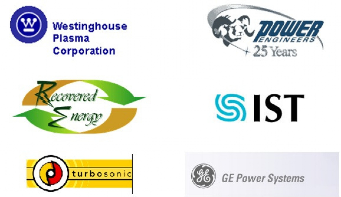
- The REI Project Team is responsible for the engineering, construction, startup and training for the Plant on a turnkey basis. The Project Team consists of Recovered Energy Inc., Westinghouse Plasma Corporation, General Electric, Innovative Steam Technologies, Power Engineers and TurboSonic, Inc., as more fully defined below. In addition, local engineers, architects, contractors and suppliers will be hired. The Project Team will use local contractors and suppliers to the greatest extent possible.
5.2 Re project team
The following Companies have been pre-selected for this Project due to their technology ownership, active participation in the development of the Plant concept and design, history in the subject field, worldwide presence and commitment to the future development of the industry.
- Recovered Energy Inc., as general project manager and overall process owner. Recovered Energy Inc. (REI) is a business development/engineering group dedicated to commercializing permanent solutions for environmental problems created by waste. In developing the Recovered Energy System™, REI has identified commercially viable and proven technologies and packaged them to offer a turnkey solution to today’s waste problem. The REI Team will perform the turnkey construction of the Plant, provide startup services and perform the initial training of the operators. There are no royalties or license fees to be paid in the future. REFCO will receive a site license and be required to sign strict secrecy agreements to protect the technology. The site license will give REFCO the right to use the technology for this Plant only. It will not apply to future expansions or additional Plants.
- Westinghouse Plasma Corporation, as the technology owner of the Plasma Gasification portion of the process. Westinghouse Plasma Corporation is the world leader in Plasma Gasification with 20 years of experience treating various types of waste, will supply the Plasma Gasification Subsystem. Additional information about Westinghouse Plasma Corporation may be found on their website at www.westinghouse-plasma.com. The contact person at Westinghouse Plasma Corporation is Dan Lazarra, phone number (724) 722-7052.
- General Electric Power Systems will supply the gas turbine and power plant technology. GE is a world leader in the production of low BTU synfuel turbines. GE will provide the entire turnkey Power Plant, including gas and steam turbines, compressors, transformers and heat recovery system, installed. The contact person at GE is Pete Bukunt, phone number (925) 750-6110.
- Power Engineers, Inc., as the project engineer. Power Engineers is a leading worldwide provider of consulting engineering services to electric utilities, independent power producers and other industrial plants. Power Engineers will supply the detail engineering for the Recovered Energy System™. Additional information about Power Engineers can be found on their website at www.powereng.com. The contact person at Power Engineers is Kevin Wallace, phone number (208) 788-3456.
- TurboSonic Technologies Inc., as the owner of the technology for the pollution control equipment. TurboSonic is a leader in the design and supply of air pollution control technologies and custom spray atomizing solutions to industrial customers worldwide. TurboSonic’s products improve performance, reduce operating costs, reduce emissions, and recover valuable by-products. TurboSonic is affiliated with and partly owned by Hamon Research-Cottrell, a leading worldwide supplier of pollution control technologies with almost 100 years of experience. TurboSonic will supply the pollution control equipment for the Recovered Energy System™. More information about TurboSonic is available on their website at www.turbosonic.com. The contact person at TurboSonic is Ed Spink, phone number 800-269-0298 ext. 214.
- Innovative Steam Technologies, as the supplier of the heat recovery system. IST has pioneered the development of once through steam generators (OTSG’s) for the safe and efficient recovery of thermal energy from high temperature gas. More information about IST is available on their website at www.otsg.com. The contact person at IST is Caleb Lawrence, phone number 519-740-0757 ext. 239.
5.3 Plant operations
The daily operations and maintenance of the Plant includes the engineers, technicians, operators, electricians, mechanics, welders, loaders, etc. that perform the daily operation and maintenance of the Plant. This function must be performed by a qualified operator approved by the Project Team. The other business functions of the Plant including overall management, sales and general administration will be performed by the Licensee. The Licensee may perform both the Management and Operational roles subject to qualification and approval by the Project Team. Long-term contract(s) (25 years) for the Management and Operational functions will be offered to the entity that manages and operates the Plant. In the event that the Licensee is not qualified (or chooses not) to operate the Plant, GE has offered to provide technical operations and maintenance for the Plant.
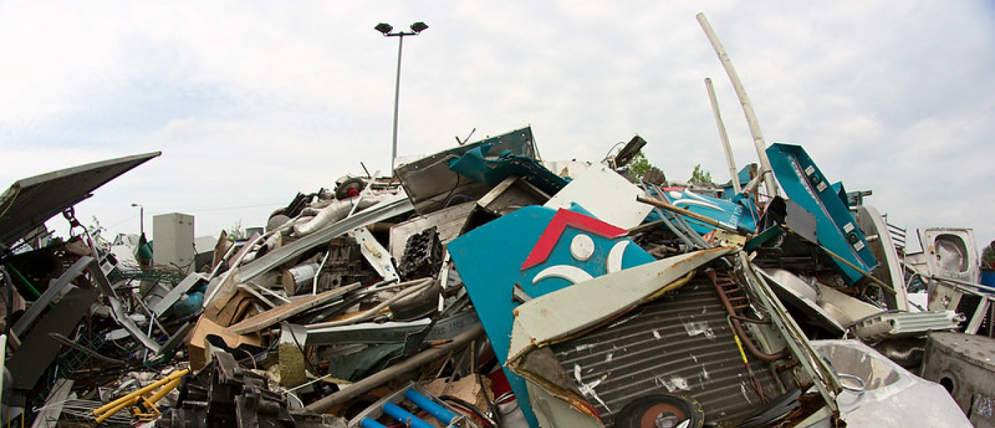
6 Market analysis
Every community in the world is struggling with the dilemma of what to do with the huge volumes of waste that are generated. Landfills are not the answer but no one seems to have a better solution. Most electricity is produced by fossil fuel, which has a significant negative impact on the environment and the generation of greenhouse gases. Green electricity makes up an insignificant percentage of the electricity produced. Pure water is a problem in every community in the world to greater or lesser degrees. REI has combined proven technologies for processing municipal waste, producing green electricity and providing purified water into a single package called the Recovered Energy System™ (RES). To the best of REFCO’s knowledge, no one else in the world is currently offering a similar comprehensive solution. However, each of the component pieces has a variety of competitors. The demand and market for each component of the system is well documented and incredibly large. No one company could begin to address all the potential customers or viable projects.
6.1 Landfills
Landfills have been the standard answer for disposing of waste for many years—not because they are a good solution but because the alternatives were not viewed as being economically viable. For many years no one understood the “true” cost of operating a landfill. Initially we just dumped waste in open pits and covered them up. After a number of years we learned that contaminants in the waste were leaching into the ground water and contaminating aquifers. Landfill gas was escaping into surrounding neighborhoods and into basements of homes. We then began to line the landfills and over time have developed fairly sophisticated liner systems. However, even the best liner system will eventually leak and cause environmental damage. During this time, a variety of programs have been developed to reduce the amount of waste going into landfills. We have developed recycling programs, composting, anaerobic digestion and a variety of other techniques to reduce the waste. However, we are still dumping most of our waste into landfills because of a lack of viable economic alternatives.
There is no other technology that can compete with the cost of a landfill, when considering only the cost to construct and operate the landfill. However, when we consider the cost of transporting waste to a distant landfill, or the cost to society for the environmental damage caused by the landfill, or the value of the land that could be used for other purposes, or the future liability of a landfill, then the “real” cost of a landfill starts to grow. Many Municipalities do not look at the “life cycle” cost of operating a landfill and are only concerned about this year’s budget shortfall. Other Municipalities have not found viable alternatives that can adequately solve the entire problem. In many cases municipalities would like another alternative but are locked into existing contracts with private landfill owners.
Landfills are now being banned or phased out by many communities. Cities like New York City and Toronto have stopped using landfills and are exporting their waste to other communities. These other communities are starting to realize the long-term cost of taking the waste. The world society is now awakening to the detrimental effects of landfills and is earnestly seeking viable alternatives.
The public rarely hears of landfill gas emissions. Since landfills occupy large areas of land, emissions control for these areas are more difficult to manage than a point source at an RES plant. The biodegradable waste in the landfill produces among other things methane gas. As a greenhouse gas methane is twenty-three times more potent than carbon dioxide. Landfill gas to energy receives renewable energy credits for providing the valuable service of converting methane into carbon dioxide. With the RES system there is an immediate and thorough conversion of the biodegradable waste in a controlled manner. Unless properly capped the emissions from landfills go largely uncontrolled. Landfills also produce a leachate that needs to be monitored and treated. The RES system eliminates landfills and the associated environmental issues. The RES system can also be used in conjunction with an existing landfill to process the landfill gas and leachate.
The Recovered Energy System™ provides a comprehensive solution to the entire problem in one system.
6.2 Power plants
The power generated by a Fossil Fuel Power Plant is generated by combusting the fuel to form heat. The heat fires a boiler, which produces steam. The steam drives a steam turbine to produce electricity at an efficiency of around 25%. That means that significant amounts of potential energy from the fuel is wasted and lost. When the carbon in the fuel is combusted it combines with oxygen to form huge amounts of carbon dioxide. Nitrous oxides (NOX), volatile organic compounds (VOC’s) and other gases are also formed in large quantities. These gases contribute to global warming.
Hydroelectric Plants do not have significant air emissions but they pose other problems. Some dams are necessary for flood control, to provide a stable source of water for agriculture and for recreation. However, Hydroelectric Plants are a threat to fisheries and there is a limit to how many our rivers can support.
Fossil Fuel, Hydropower and Nuclear Plants currently provide most of the world’s electricity. The world recognizes that the production of power from traditional technologies causes serious negative environmental consequences and they are depleting our natural resources and won’t last forever. Governments around the world are demanding industry to produce more power from renewable energy sources. Quotas have been established, incentives have been offered and grants have been provided to help develop plants to produce power from wind, solar, geothermal and waste sources. Wind, solar and geothermal power is too expensive and not always practical or available. Incinerators were built to convert waste into energy in an inefficient manner.
The Recovered Energy System™ represents an economically viable way to convert waste into electricity without any of the negative environmental impacts of other technologies. Waste is readily available in every community. The waste in most communities can provide up to 1/3 of the community’s total power requirements. The Recovered Energy System™ does not contribute to the greenhouse effect and utilizes a renewable energy source that will always exist.
6.3 Greenhouse gas emissions
Nature has provided a balance. Humans and other animals breathe oxygen and release carbon dioxide. Plants use carbon dioxide and release oxygen. As long as that balance maintains itself everything is perfect. However, when we mine fossil fuel and burn it we release carbon dioxide and other gases that were not intended to be released and we upset the balance of nature. Global warming is taking place because greenhouse gases are increasing in an unbalanced manner. The impact of greenhouse gases will continue until society finds an alternative to fossil fuel electricity.
The earth’s atmosphere contains various gases including carbon dioxide (CO2), methane (CH4), nitrous oxide (NO2) and chlorofluoro-carbons (CFC’s) which absorb infrared radiation emitted from the earth’s surface. Higher concentrations of these gases in the atmosphere relate to increased absorption capacity for infrared radiation. Because control of the earth’s overall surface temperature depends on a balance between incoming sunlight energy (constant) and re-radiated infra-red energy, a net increase in atmospheric absorption of energy causes a net increase in the earth’s temperature. This is the cause of the “greenhouse” effect with its associated global warming from additional amounts of greenhouse gases (GHG’s).
The relative contributions of specific GHG’s to global warming also vary. Carbon dioxide is the most abundant GHG in the atmosphere and is used as a basis to describe GHG emissions. For example, CH4 equals 21 CO2 equivalents; N2O equals 310 CO2 equivalents, etc.
Certain of the GHG’s are naturally produced (CO2 and CH4) while others (N2O and CFC’s) are primarily man-made (anthropogenic). In addition to the natural (biogenic) sources of CO2 and CH4, substantial increases of these have occurred over the last century due to anthropogenic sources. All Fossil Fuel Power Plants are anthropogenic sources of GHG’s.
The Recovered Energy System™ using plasma gasification of waste has a positive impact on greenhouse gases, because it reduces the dependence on fossil fuel. CO2 released in the exhaust from the plant is not new CO2 since it will be released anyway from the landfill and comes from already existing sources of carbon.
6.4 DISASTER security
In the event of a chemical or biological attack or a biological crisis such as mad cow disease, there is currently no place to destroy the contamination that would result. As an example, incineration does not destroy the prions (proteins) in mad cow disease. Scientists in England, where they burned piles of infected cattle, believe they may have made matters worse and made the proteins airborne. Plasma Gasification is the only system that has high enough temperatures to destroy the risk. Large Municipalities should have a local means of both biological and chemical hazardous material destruction that can process large quantities of materials. Currently no city in the world is prepared to destroy tens of thousands of tons of infected materials. Plasma is the most complete and comprehensive form of destruction. Since the RES system does not require size reduction for anything less than a meter the RES system is well suited for an incident response capability that is safe for the operators and the environment.
6.5 Pure water
Fresh water makes up only a few percent of the world’s total water supply. Compound that with the fact that our fresh water is being polluted from landfills, past dumpsites, and other factors and it is clear that the lack of safe drinking water is reaching a crisis situation in many Municipalities.
Natural spring water is becoming hard to find and wells are becoming more contaminated. Most fresh water is not drinkable without some form of processing.
The Recovered Energy System™ can produce pure distilled water and even purified bottled drinking water using waste steam. Therefore the system incurs a very small energy cost to produce pure water, giving the system an economic advantage over other similar water treatment plants. The process will compete very favorably with any Municipality that is currently treating water or desalinating water. This feature of the Recovered Energy System™ is not required for communities that have well water or spring water that requires minimal treatment. Since this is an optional component of the Plant it can be used where it makes sense and can improve the economics of the Plant but is not required for the project to be viable.
6.6 Processes for handling waste
There are hundreds of companies that have been trying to address the waste problem for years. The more common technologies can be grouped into the following categories:
6.6.1 Sorting and Recycling
A number of companies offer technologies to sort the waste. The objective is to recover as much paper, cardboard, metal, plastic and other recyclable products from the waste as possible. The recycled waste is then sold to manufacturers who recycle the waste into their manufacturing processes. Some WTE facilities cannot handle raw municipal waste and they require a sorting process on the front end of the WTE facility. The purpose of the front end processing is to prepare the waste into a more usable waste product called “Refuse Derived Fuel” or “RDF”.
The Recovered Energy System™ does not need RDF and does not require any form of front end processing system. However, REI does not discourage recycling and is happy to take the waste after the recycling process is finished. Sorting and recycling centers are synergistic with the Recovered Energy System™ and will never compete with REI. REI offers the community an alternative recycling method.
6.6.2 Biological Processes
Biological technologies, including composting and anaerobic digestion are used to decompose biomass. The end result is fertilizer, some electricity and some processes can produce ethanol. Biological processes can only deal with a small portion of the overall waste problem. They require significant sorting of the waste and the processes are slow. Biological processes will never be a significant factor in the industry, but they will continue to make a contribution in specific applications.
6.6.3 Pyrolosis
Pyrolosis is the breaking down of matter into char, tars, oil and hydrocarbon gas in the total absence of oxygen. The end products of pyrolosis are carbon black, oil that can be sent back to a refiner and some hydrocarbon gases that can be used to make steam or electricity. A common example of a pyrolosis process is charcoal briquettes. Most pyrolosis systems are very selective in the type of material they can process. A few processes have been developed that use pyrolosis for processing tires. They cannot handle the wide variety of waste that exists and will only have a small impact on the overall processing of waste.
6.6.4 Small-scale Gasification
Gasification has been around for 10,000 years. Coal Gasification was used in the 1700’s in England, France and Germany for street lanterns. During World War I small gasifiers were developed to operate vehicles, boats, trains and electric generators. During World War II 90% of the vehicles in Sweden were powered by gasifiers. Small gasifiers became unpopular when oil became cheap and plentiful. In recent years there has been resurgence in gasifiers for various applications.
There are at least 50 companies that claim to have a Commercial Gasification Process, some of which have operating Plants and some of which only have prototypes. Waterwide is probably the most noted of these with over 40 installations worldwide. The primary application for these gasifiers is the processing of wood waste and biomass. At least one company has a Plant in China that is processing MSW. Most of these systems can process between 1-3 tons per hour in a single reactor. They can be either updraft or down draft gasifiers. Most of them involve a grate system and are pressurized. The material that feeds into the reactor must be uniformly sized, relatively dry and must be sorted. Most gasifiers require an RDF plant on the front end to prepare the fuel. These gasifiers operate at relatively low temperatures and produce high levels of tar and char. Most of them go straight to a combustor where the synfuel is combusted and a boiler generates steam that is used to fire a steam turbine. A few processes clean the gas first and can then go to an engine (“genset”) or to a small gas turbine. These gasifiers cannot process large volumes of MSW or other waste because the reactors are too small and it would take too many of them to be practical. These gasifiers do not pose a competitive threat. Even though these gasifiers have been around for many years and marketed by at least 50 companies, there are relatively few installations and they have never been widely accepted.
6.6.5 Integrated Gasification Combined Cycle (IGCC)
IGCC gasification of coal and various petroleum products has become very popular in recent years as an alternative to Coal Fired Power Plants. They are cleaner than traditional Coal Fired Power Plants and can handle large volumes. One of the leaders in the industry is Texaco, who will build a battery limits Coal Gasification Plant for about $1,700 per installed kWh of capacity. Other technologies can go as high as $2,500 per installed kWh of capacity and some suppliers are claiming costs as low as $1,200 per installed kWh of capacity. Almost all Coal Power Plants that are currently being installed around the world are IGCC Gasification Plants. The industry grew 50% from 1990 to 1999 and is growing about 10% per year. The synfuel that is produced can either be used to produce power or chemicals such as methanol. About half of the world capacity is used for chemicals and the other half for power. The trend, however, is toward power.
Air emissions from IGCC Gasification Plants are far below U.S. Clean Air Standards. Sulfur removal and emissions of sulfur dioxide, NOX and carbon monoxide are far below normal coal fired power plants, incinerators, combustors and most other gasifiers. However, they still contribute significantly to the “greenhouse effect” because all the gases they emit are new greenhouse gases.
In principal, an IGCC Gasification Plant is very similar to a Recovered Energy System™ Plant. There are, however, a few differences. The reactor for an IGCC Gasification Plant is pressurized and in general requires pure oxygen. The RES Plant has an option of using either normal air or pure oxygen. The use of oxygen reduces the size of the reactor but an oxygen plant is very expensive and dangerous. The BTU value of coal is 2 to 3 times that of municipal waste. Therefore, when considering both the BTU value and the impact of oxygen, the reactors for an IGCC Gasification Plant are about ¼ the size of an RES reactor to process the same volume of waste. The pollution control equipment is similar other than the size difference. The synfuel from a large-scale gasifier has a higher BTU value than the synfuel from the RES process, which makes the turbine combustor different and an IGCC Gasification Plant has the compressor on the front end whereas the RES has the compressor just in front of the gas turbine.
It would be possible for an IGCC Gasification Plant to use MSW as a feedstock with some modifications to the system. Various IGCC gasification companies have considered the possibility but they have not yet refined the feed system for MSW and they would also require drying, sorting and the use of RDF. Currently over 98% of all IGCC Gasification Plants use coal, petroleum coke, fuel oil, refinery tars or natural gas as a feedstock
Until the IGCC gasification industry decides to channel their efforts differently they do not represent competition. Competition from IGCC gasifiers, however, could come in the future. IGCC gasifiers are inferior to plasma gasifiers for the following reasons:
- IGCC Gasification Plants can pay anywhere from $10 to $40 per ton for the coal or petroleum products as a feedstock. By using waste as a feedstock the feedstock has no cost and, in fact, customers will pay a tipping fee to dispose of the waste.
- Gasification of coal or petroleum products continues to contribute to the “greenhouse effect”. The world will continue to produce greenhouse gases until we figure out a way to be less dependent on fossil fuels.
- IGCC Gasification Plants are currently designed for a specific fuel. The RES process is designed to take any type of fuel
- Plasma gasifiers operate at higher temperatures, produce fewer emissions and have less of an impact on the environment.
IGCC Gasification Plants have a distinct capital cost advantage at this time because they have reached a level of maturity as an industry. When they first began their capital cost was high. Given time plasma gasification systems will come down in cost as all technologies do. However, the world cannot continue to rely on coal and other fossil fuels for electricity.
6.6.6 Waste to Energy (WTE) Combustion Processes
As of 2000, there were approximately 102 Waste-to-Energy facilities using some form of combustion process operating in 31 states in the United States. These WTE facilities include the following technologies:
- Mass Burn (MB) WTE Plants generate electricity and/or steam from waste by feeding mixed municipal waste into large furnaces dedicated solely to burning trash and producing power. 70 of the 102 WTE facilities in the U.S. utilize this process.
- Refuse-derived fuel (RDF) WTE plants remove recyclable or unburnable materials and shred or process the remaining trash into a uniform fuel. A dedicated combustor, or furnace, may be located on-site to burn the fuel and generate power; or the RDF may be transported off site for use as a fuel in boilers that burn other fossil fuel. 19 of the 102 WTE facilities utilize this technology.
- The remaining 13 WTE facilities are Modular WTE Plants, which are similar to Mass Burn plants, but are smaller mobile units that may be quickly assembled where needed.
These WTE Plants currently process more than 30 million tons of trash each year or about 14% of America’s solid waste. Electric power generated by these plants is approximately 2,816 megawatts per hour. These technologies are the most widely used technologies for converting large volumes of municipal waste into energy.
The average capital investment for WTE combustion plants is $3,570 per installed kWh of capacity.
Major operators of WTE Plants in the U.S. include:
- Covanta Energy Solutions. Covanta is the world’s leading operator of large-scale WTE facilities with 26 facilities in 16 states and one facility in Italy. Covanta’s facilities can process over 32,000 tons per day of waste and produce more than 800 megawatts of electricity. At design capacity, this is about .6 megawatts per ton of waste (gross) or .54 megawatts (net – after 10% reduction for internal use).
- Wheelabrator Technologies, Inc. Wheelabrator is a wholly owned subsidiary of Waste Management. Wheelabrator has 16 WTE Plant with 671 megawatts of installed capacity and processing 23,750 tons per day of municipal solid waste. At design capacity, Wheelabrator’s Plants can produce approximately .68 megawatts per ton of waste (gross) or .61 megawatts (net – after 10% reduction for internal use). Wheelabrator Plants have involved about $2.2 billion in invested capital or $3.3 million per installed megawatt.
- American Ref-Fuel operates 6 large WTE Plants in the Northeast U.S. These Plants have a design capacity to produce over 13,600 tons of waste per day and 364 mWh of electricity. This equates to approximately .64 tons of waste per megawatt of electricity (gross) or .58 megawatts (net- after 10% reduction for internal use).
These three companies account for more than half of the domestic capacity for waste processing and power production.
Typical plant performance of WTE Combustion Plants is as follows:
- Combustion temperatures can be as high as 2000° F with high combustion efficiency and CO emissions of 15 to 40 ppm. Reactor exit temperatures are less than 1200° F.
- Waste VOLUME reduction of 90%, depending on the type of waste. The amount of ash on a WEIGHT basis is as high as 25% of the input. The ash from earlier plants was considered toxic and required disposal in a class B landfill. However, with higher operating temperatures the ash is generally considered non-hazardous for all plants that have made the environmental changes. A small portion (<4%) of the ash is used in roadbeds and for other uses, however, the vast majority has to be disposed of in a landfill.
- Emission systems now satisfy current EPA emission requirements. Early Plants (historically referred to as “Incinerators”) did not have adequate emission control devices and had very high emissions and gave the industry a bad reputation. Most Plants have either upgraded their emission control systems or have been forced out of business. WTE Plants still produce high levels of tars, dioxins, furans and char when compared to the air emissions from IGCC plants or the Recovered Energy System™. However, WTE Plants prevent the release of new greenhouse gasses. WTE Plants prevent the release of more than a million tons of methane into our atmosphere, assuming the same amount of trash now processed at WTE facilities is disposed in a landfill without methane recovery.
Most of the WTE facilities in the U.S. became operational between 1980 and 1996. Only three new Plants have come on line since 1996 (2 in 1997 and 1 in 2000). To our knowledge, there are no new Plants currently under construction. The primary reason for the slow-down in new WTE Plants is the environmental concern involving existing plants. Most of these Plants were installed without adequately addressing the environmental issues. Due to new emission standards some of these facilities have closed while the majority is undergoing major renovation. The WTE industry is currently in the middle of an $800 million plant upgrade to install adequate air quality control systems that will allow the facilities to meet current EPA standards. Because of their historical emission problems, the Incinerator Plants have received and continue to receive significant resistance from environmental groups and negative reviews in the press. WTE Combustion processes have the following disadvantages when compared to the Recovered Energy System™:
- Emissions of tars, furans, dioxins, char, VOC’s, particulates and SOX are higher.
- Combustion processes can only produce steam and electricity, whereas the synfuel from a gasification process can be used for many other applications. These processes use steam turbines are only half as efficient as combined cycle gas/steam turbines that are used by the RES.
- All of the inorganics contained in the waste come out as ash, which contains char and tars. The amount of inorganics can be as much as 25% by weight which means that landfills will continue to be required to dispose of the ash. The ash has very little use except as a road base because even though it is considered non-hazardous it still has an environmental impact and very few people will use it. The vitrified glass from the RES process has no environmental impact and can be used in numerous applications.
- Most WTE facilities require some form of pre-sorting. In order to reduce the volumes of ash, inorganics are sorted out. They cannot handle all types of waste.
WTE Combustion technologies do not pose a serious competitive threat to REI. Incinerators have a very bad reputation and have been banned in many parts of the world. No new plants are under construction. It will take a significant effort to clean up the existing plants before these technologies can change public sentiment. However, the new technologies do have good processes that are relatively clean and efficient. If they can ever overcome the bad reputation they could begin to build Plants again.
6.6.7 Plasma Gasification Processes
Plasma Gasification has been used commercially for over 20 years to process waste. It was originally developed for the steel industry to melt iron. It has also been used to process hazardous waste, medical waste, PCB’s, auto shredder residue, tires, radioactive waste, incinerator ash and other difficult waste. Plasma Gasification Systems use an external source of energy to increase the gasification temperature. Because of the high temperatures they achieve a better destruction of the waste, fewer emissions and a cleaner process.
There are at least 15 companies that offer Plasma Gasification processes. Many of them have been funded by the DOE and other grant programs. The leader in the industry with the most experience is Westinghouse Plasma Corporation, a private company that was spun off by Westinghouse Electric Corporation. Over the past 20 years, Westinghouse Electric Corporation and now Westinghouse Plasma Corporation have been involved in at least 40 projects. The other companies combined have at least that many more projects. All of the plants, other than the steel industry Plants, have been small. There are a number of Plants in Japan, most of which are processing incinerator ash. Two Plants in Japan are processing MSW and auto shredder residue. Currently there is no Plasma Gasification Plant operating anywhere in the world that is processing large volumes of municipal waste.
Westinghouse Plasma Corporation does not offer Turnkey Plants—they only offer the plasma gasification island. The balance of Plant must either be designed by the customer or by some other engineering firm. REI has worked with Westinghouse Plasma Corporation and other prominent suppliers to design a Turnkey Plant based on the Westinghouse Plasma Corporation Plasma Gasification System. A more complete description of the Recovered Energy System™ is included in Exhibits 2 and 3.
6.6.8 Hybrid Processes
Thermoselect has a hybrid process that uses natural gas torches to create a higher temperature reaction. The concept is similar to a plasma gasifier but the mechanism is different. The process also requires the use of pure oxygen. The gas cleanup system is similar to REI’s. The process will handle virtually any type of waste. Thermoselect has a 300 tpd Plant operating in Japan. Another Plant in Germany has been closed down due to environmental and legal issues. The disadvantages of the Thermoselect plant when compared to the Recovered Energy System™ are as follows:
- Thermoselect exports 400 kW of electricity per ton of waste compared to 1,000 kW of electricity for every ton with the RES.
- Thermoselect requires an Oxygen Plant.
- The torches require a significant amount of natural gas, which is not recovered into energy in any form.
Thermoselect has proposed a Plant for Puerto Rico capable of processing 3,000 tons of waste per day. The Plant will produce about 45 mWh of electricity. The total cost of the Plant is about $500 million. The cost per installed kWh of capacity is $11,100. REFCO is proposing to provide a Plant capable of processing 2,500 tons per day of waste, which will produce 115 mWh of electricity. The cost per kWh of installed capacity for the RES Plant is $4,623. In addition the RES Plant will produce 2.2 million cubic meters of pure distilled water per year.
7 Analysis of the technology
7.1 Plasma gasification
A thorough analysis of all the factors and data will support a conclusion that Plasma Gasification is the best available technology for the management of waste and the only known technology capable of solving the entire municipal waste management problem. The reason for this is simple—Plasma Gasification is the only process that has enough heat to break down all the organic compounds and to also process the inorganic waste.
Plasma Gasification is not a new technology. It has been in continuous operation for over 20 years. However, until now Plasma Gasification has been used in the steel industry and for processing hazardous waste, medical waste, nuclear waste, PCB’s, ash from incinerators and other difficult waste streams.
Westinghouse Electric Corporation developed their Plasma Gasification Process about 20 years ago. Between them and Westinghouse Plasma Corporation, they have supplied Plasma Gasification Systems for 40 projects. They have tested a wide range of waste material. The Westinghouse Plasma Corporation Plasma Gasification Process has been proven in numerous applications. Hitachi has built 3 Plants in Japan using the Westinghouse Plasma Corporation processes that are currently operating partially on municipal solid waste. The first Plant in Joshii, Japan was commissioned in July 1999 and processes about 50 tons/day. The second Plant in Utashinai, Japan processes about 300 tons/day of MSW and ASR (auto shredder residue). The third Plant in Mihama, Japan processes about 300 tons/day of MSW and sewage sludge.
Until now no one has applied the Westinghouse Plasma Corporation Plasma Gasification System to large volumes of municipal waste (more than 500 tons/day). There is no good technical reason why, only financial reasons. REI has now combined the Westinghouse Plasma Corporation system with other known and proven technologies to design a complete Plant capable of processing large volumes of municipal waste, produce significant amounts of electricity and produce large volumes of clean water. The complete system is called the Recovered Energy System™. The key to the overall viability of the RES concept is the integration of multiple technologies with an ability to adjust to different economic drivers.
7.2 Power plant
A combined cycle gas/steam turbine is the most efficient method to produce power currently available, with efficiencies as high as 56%. Gasification of coal integrated with a combined cycle power plant (referred to as an IGCC Plant) has become the preference for the production of electricity from coal. IGCC Plants are cleaner and more efficient than conventional Coal Plants. IGCC Plants gasify coal to produce a syngas. The syngas then goes to a gas turbine that produces electricity. The heat from the turbine goes to a heat recovery steam generator that produces steam. The steam goes to a steam turbine that produces more electricity. The combination of a gas turbine with a steam turbine is called a Combined Cycle Power Plant.
The syngas produced by the gasification of coal has a BTU value of 300 BTU/scf assuming an Oxygen Blown Plant. In some cases the nitrogen from the oxygen plant is added back lowering the BTU value to 125 BTU/scf. The BTU value of natural gas is 1000 BTU/scf. Gas turbines were originally developed to run on natural gas or distillate. With the development of the coal gasification industry the turbine manufacturers modified the combustors in the gas turbines to accept low BTU syngas either instead of or in combination with natural gas or distillate.
Alstom, Siemens-Westinghouse and General Electric all developed turbine models that were designed for low BTU syngas applications.
Alstom developed the GT11N2 gas turbine specifically for the syngas from blast furnace gas. It operates on syngas ranging from 70-130 BTU/scf. It has an output of approximately 120 mWh (50 or 60 cycle) under ISO conditions with a design combined cycle heat rate of approximately 7,000. Alstom has 2 plants operating on low BTU syngas.
Siemens developed the V94.2 and V94.3 turbines for the coal gasification industry. These are 50 cycles turbines with a combined cycle output of approximately 250-300 mWh and heat rates of approximately 6,300. Siemens has 5 plants operating in Europe on coal gasification syngas.
General Electric has developed the following gas turbines for low BTU syngas:
- MS 6001B with a combined cycle output of about 60 mWh (either 50 or 60 cycle) and a heat rate of 6,900. 4 installations. The newer version of this turbine is the MS6001C turbine.
- MS 6001FA with a combined cycle output of about 110 mWh (either 50 or 60 cycle) and a heat rate of approximately 6,300. 6 installations.
- MS 7001FA with a combined cycle output of about 250 mWh (60 cycle only) and a heat rate of approximately 6,100. 2 installations.
- MS 9001E with a combined cycle output of about 190 mWh (50 cycle only) and a heat rate of approximately 6,600. 10 installations.
- MS 9001FA with a combined cycle output of about 380 mWh (50 cycle only) and a heat rate of approximately 6,000. REI has concluded that this turbine is too large and does not work within the structure of this business plan. It would work well for a large plant processing more than 5,000 tons of waste per day with a 50 cycle application.
- The above turbines are all frame turbines. The combustors are designed to operate on syngas or a combination of syngas and natural gas. The syngas can have a BTU value ranging from 120 to 300. The combustors are all 14” diameter for the 6, 7 and 9 FA turbines and 10” diameter for the 6 B and C turbines.
- GE has tested the LM 2500 and LM 6000 turbines on syngas but has no installations. The LM turbines are aero derivative turbines and do not have the experience or flexibility of the frame turbines. REI will not use these turbines at this time.
The gas turbine is the most critical and sensitive component in the Recovered Energy System™. REI has concluded that GE has the best range of turbines, the most experience with syngas and the most flexibility with their turbines. REI has chosen to work with the GE line of syngas turbines. REI will use the following turbines for different size plants:
- 500 tpd plant MS 6001B or C turbine (50 or 60 cycle)
- 1,000 tpd plant MS 6001FA turbine (50 or 60 cycle)
- 2,500 tpd plant MS 7001FA turbine (60 cycle) or (2) MS 6001FA turbines (50 cycle)
The gas turbines operate on a combination of natural gas and syngas. They need a minimum of 30% syngas and a maximum of 70% syngas. REI has determined that the best range is to be between 45-60% syngas and has sized the various size plants to fit within this range. That means that part of the fuel for the Power Plant comes from natural gas and part from syngas. This allows for the maximum efficiency in the turbine and the best economics for the project. It also provides for future expansion of the Gasification Plant.
The Power Plant includes a duct burner that will duct burn the syngas until it reaches 30% of the total flow. Once the syngas reaches 30% the syngas will go to the turbines. The Plant will automatically control the flow of syngas and natural gas in the proper ratio to achieve the optimum operating conditions of the turbine. During full operations, the duct burner can be used to burn additional natural gas during peak power demand hours to produce up to 25% more power. This power can be requested by the local utility on a demand basis.
7.3 Others equipment
In developing the Recovered Energy System™, REI has used well-known suppliers and proven equipment with similar applications.
- The pollution control equipment is standard equipment used by Coal Gasification Plants, Incinerators and Coal Fired Power Plants. The selection of which equipment to use and location in the plant may vary slightly but the application is the same.
- The gas cooler is a standard once-through steam generator that is the same as those supplied for many years to Power Plants and other Industrial Plants.
- The gas compressors are standard Kobelco screw compressors.
- Every piece of equipment that is being used by the RES is currently being used in a similar application at similar capacities and technical requirement. REI has used large companies that can provide meaningful process guarantees.
Additional technical information about Plasma Gasification and the Recovered Energy System™ is included in Exhibits 1 and 2.
8 Plant operations
The waste will come to the facility, will be weighed on scales and then dumped onto a tipping floor. The facility will include about 4 days worth of waste storage in pits. Hydraulic arms with grapple hooks will pick up the waste and dump it into hoppers. No sorting is required and no shredding is required for anything less than 1 meter in diameter. Shredding will be available for large oversize items only.
The hopper feeds a hydraulic ram that pushes the waste directly into the reactor. Plasma torches in the bottom of the reactor provide the external heat required for complete gasification and breakdown of the matter. The inorganic material settles to the bottom of the reactor where the temperatures are as high as 5000° F. Metals are melted and other inorganic matter is vitrified into glass. The molten metal and glass flows out the bottom of the reactor. The organic matter is gasified and forms a gas composed of carbon monoxide, hydrogen, nitrogen and water. Chlorine, sulfur, particulates and some metals are also contained in the gas. The gas is cooled using a series of heat exchangers. The heat is used to make steam, which goes to the steam turbine. The cool gas is then cleaned. The gas first goes to a cyclone, which removes about 85% of the particulates and a small amount of the metals. The gas then goes to a wet chlorine scrubber, which removes 99.9% of the chlorine in the form of hydrochloric acid and 98% of the remaining particulates and metals. The gas then goes to a wet electrostatic precipitator, which removes 99% of the remaining particulates and metals. The moisture is then removed from the gas. The gas then goes to a biological sulfur removal system that produces fertilizer grade sulfur. The gas has gone through three (3) redundant emission control systems and is now a clean synfuel.
The Power Plant will be a combined cycle gas/steam turbine system supplied by GE. The GE turbine uses a specially designed combustor that will burn either low BTU synfuel or natural gas.
The operation of the Power Plant is almost identical to the operation of any natural gas combined cycle plant except that the synfuel needs to be cleaned and compressed to be burned in the gas turbine and this equipment needs to be maintained.
The Water Distillation System is a multi-effect distillation system supplied by IDE. IDE has hundreds of systems operating all over the world, virtually maintenance free. IDE is a leading supplier of distillation systems using low-pressure steam. Their systems are currently processing all types of source water, including salt water, lake water, river water, canal water, and brackish water.
All of the equipment supplied as part of the Recovered Energy System™ has been selected because of its simple operations, history of reliable operation, history of minimal down time for maintenance and ease of operation and maintenance. The entire system is designed with a minimal amount of moving parts, very few conveyors, simple feed systems and a streamlined operation. Compared to similar plants, the process is simple and straightforward.
A more complete description of the process is shown in Exhibit 2.
9 Financial projections
Financial projections have not been provided with this Business Plan because the specific Project fees and parameters have not been established.
Financial projections have been prepared for each of the alternative pricing combinations shown in Section 4 of this Business Plan to verify that the minimum profit criteria for the Financial Partner can be satisfied. The final negotiated prices for any specific project will be analyzed to make sure that the projected profits will meet the standards established for securing the loan.
Based on the various combinations included in the pricing table shown in Section 4 the annual operating income is projected to exceed $50 Million USD. The actual net profit may vary depending on wage rates, construction costs, raw material costs and other factors.
The portion of the profits belonging to the Licensee can be used by the Licensee in any way it wishes to. The portion of the profits belonging to the non-profit entity will be used for humanitarian purposes within the general community to fund community projects such as schools, hospitals or low-income housing.
Full financial projections will be provided to the appropriate parties as part of the Feasibility Study, once the specific parameters are established for the Project.
REFCO has tried to develop a program that meets the financial criteria, requires the lowest prices possible from the Municipality and provides the maximum benefit back to the community.
REFCO will continually be looking for ways to improve the profitability of the Project. Some of the alternatives for improving the profitability include processing of higher value waste, achieving better utilization of the Plant, developing markets for building materials produced from the glass and expanding the Plant.
The objective of the Business Plan is to provide a comprehensive, financially attractive solution to make better use of the waste, with a positive environmental impact in a way that will make the Plant economically viable for the long-term and provide meaningful humanitarian benefits to the community for the life of the Project.
10 Risk analysis
10.1 Political risk
Given the current political issues with landfills, greenhouse gases and emissions from fossil fuel power plants, one must also take into account the political risk of doing nothing, especially when there is no financial risk in this Business Plan for the Municipality.
The Business Plan has been designed to eliminate the risks for all parties to the greatest extent possible. The completion of the Project is protected by a performance bond by the general contractor. The process is guaranteed by performance guarantees. The overall cost is guaranteed. The Power Plant is a standard Power Plant that can be operated independently using natural gas if necessary. The Water Distillation System can be operated in conjunction with the Power Plant only.
The political benefits that will be realized in the form of permanent job creation, construction jobs, elimination of landfills, environmental benefits and profits certainly outweigh any perceived risk.
10.2 Social issues
Environmental groups throughout the world are opposed to almost all new technology. Many people will not understand the nature of this technology and will not take the time to understand it before they react. Some will associate the Plant with incinerators and will immediately form negative opinions. In order to minimize the impact of social groups REFCO will lead a significant public awareness and educational campaign.
10.3 Technical risks
The application of Plasma Gasification for large volumes of standard municipal waste is a new application of the technology, thereby raising a technical risk. This risk has been addressed by the following factors:
- The Power Plant can operate on a dual fuel of either synfuel or natural gas or diesel fuel.
- Each of the components of the Recovered Energy System™ is supplied by a known and recognized supplier. Each component is currently in operation in multiple similar applications with known and proven track records.
- None of the components represent a scale up of the technology. Each component is in current use in similar operations of similar size and scope.
- Each of the components of the Plant come with standard construction warranties and process guarantees by well established and financially sound suppliers.
- REFCO and its suppliers guarantee the overall Project cost.
- The construction of the Plant will be done by a large, internationally known general contractor capable of providing an adequate performance bond with guarantees for completion of the Plant.
Exhibit 1
Technical discussion of why plasma gasification is the only answer
Definition of Combustion/Gasification
The above chart shows a simplified, representative gasification/combustion curve for typical municipal solid waste (MSW). (Note that every compound has its own curve, the actual curves are not straight lines and the curves will not have the same starting and ending points, however, this chart is intended to be a simplified representation to illustrate a concept.) The X axis shows the progression of MSW to gasification and then combustion. The Y axis shows the initial energy contained in the waste, the energy required to gasify MSW and then the energy released by the combustion of MSW. The chart shows three curves—one representing all matter that will break down at temperatures up to 1000 degrees Fahrenheit, one representing all matter that will break down at temperatures up to 1500 degrees Fahrenheit and one representing all matter that will break down at 2000 degrees Fahrenheit. The formulas for the reactions that are taking place are as follows:
Chemical Formulas InvolvedChemical composition of typical MSW: CH1.6 O.6
Objective of pure gasification CH1.6 O.6 + .3O2 = CO + H2
Objective of pure combustion (incineration) CH1.6 O.6 + O2 = CO2 + H2O
Chemical composition of tars CxHxOx or CxHxNx
Chemical composition of hydrocarbon gases CxHx
Description of the Gasification/Combustion Processes
Combustion requires three essential elements—combustible matter, an ignition source and oxygen. Combustion cannot occur until the matter is first broken down and then gasified. Think of starting a campfire. In order to start the fire you must use a match or some form of heat source. The match gasifies a portion of the wood or paper, the gas then combusts (ignites) and burns. The heat required to gasify is less than the heat generated by combustion. Therefore, once the fire starts it generates enough of its own heat to gasify and then ignite the rest of the wood and release energy in the form of heat. Without oxygen combustion cannot occur. Gasification, therefore, is a precursor to combustion.
In a perfect world, assuming pure gasification, carbon is combined with limited oxygen in the presence of heat to form carbon monoxide (CO) and hydrogen (H2). The oxygen required for gasification is less than 30% of the oxygen required for combustion. Once gasification has occurred, three times more oxygen is added to cause combustion. The result is carbon dioxide (CO2) and water (H2O).
The objective of a gasification process is to convert the carbon and hydrogen in the waste to a fuel gas composed of CO and H2 and not to combust any of the waste. The fuel gas still contains most of the chemical and heat energy of the waste. Once cleaned the fuel gas has a variety of uses. The only way to achieve pure gasification is with an external heat source.
In practicality there is no process that can achieve pure gasification, although the Recovered Energy System™ Plasma Gasification Process comes closer than any other known technology. The Recovered Energy System™ uses a patented plasma torch to provide the energy required for gasification. The equipment design, combined with a proprietary control system allows the process to control the reaction so that there is very little combustion and a high level of control of the reaction. The plasma torch heats air to internal temperatures (inside the torch) as high as 25,000 degrees Fahrenheit and external temperatures (point of contact with the material) as high as 8,000 degrees Fahrenheit. The Recovered Energy System™ produces a clean fuel gas that has a variety of other uses.
Normal gasifiers use partial combustion in order to generate the heat required for gasification. Partial combustion causes the formation of tars and dioxins in the fuel gas and results in the loss of a substantial amount of the energy. The temperatures that can be achieved in the reaction process are much lower than with Recovered Energy System™ and there is much less control of the reaction. Normal gasifiers produce an inferior fuel gas that is high in CO2 and various contaminants. Most gasifiers have not been successful in cleaning the gas and therefore immediately combust the gas and produce steam that can only fire a steam turbine.
The objective of an incinerator is to achieve complete combustion. The heat from the combustion can only be used to make steam or to go to a steam turbine. In the real world, incinerators fall far short of complete combustion. They also produce tars and dioxins and lose a substantial amount of the chemical and heat energy.
The amount of combustion that takes place in any process is measured by the amount of carbon that is converted to CO2. Normal gasifiers convert 33-56% of the carbon to CO2 (based on a study of 15 gasifier processes). Modern incinerators convert 95% of the carbon to CO2. The Recovered Energy System™ converts less than 7% of the carbon to CO2 —just enough to ensure full gasification. With the Recovered Energy System™ some of the energy produced is required to operate the plasma torches. The amount of the energy used to generate the electricity for the torches is equivalent to less than 8% of the carbon, leaving a net amount of carbon converted to CO2 in the Recovered Energy System™ of 15%--less than half the carbon used by normal gasifiers.
Energy Produced:
The total energy produced by Plasma Gasification, normal gasification and incineration can be measured by the area under the curve. The charts to the left show the energy produced by each of these processes.
The normal gasifier curve shows the chemical energy left assuming perfect combustion, which is not possible. It is possible for a normal gasifier to recover part of the energy generated by combustion by converting the sensible heat from the discharge of the reactor to steam. However, most gasifiers do not recover this energy.
The curve for incinerators shows the energy that is generated by combustion. Incinerators can never recover the energy that is contained in the noncom-busted matter.
The curve for the Recovered Energy System™ factors in the carbon converted into electricity that is needed for the plasma torches. The small amount of energy that comes from combustion is partially recovered by converting the sensible heat from the discharge of reactor to steam. The Recovered Energy System™ recovers almost all of the sensible heat in the fuel gas. Our process produces higher energy because (a) we are on a higher curve, (b) we recover most of the sensible heat (c) we lose very little to combustion and (d) we can use a more efficient gas turbine system.
The bottom line is as follows:
Net electricity produced by the Recovered Energy System™ >1 mWh/ton of waste
Net electricity produced by gasifiers and incinerators .4 to .6 mWh/ton of waste
Formation of Tars, Char and Hydrocarbon Gases
Before either gasification or combustion (incineration) can take place the organic matter has to be broken down. The breakdown of the matter produces tars (defined as any hydrocarbons that will condense—including furans, phenols, etc.), char (residual unburned carbon), hydrocarbon gases (such as methane, ethane, etc.) and dioxins.
Tars:
Tars are various molecules of carbon, hydrogen and oxygen or nitrogen. Tars are formed at various temperatures starting at 450 degrees Fahrenheit up to 1800 degrees Fahrenheit. Tars can be classified as Primary and Secondary tars. Primary tars begin forming at approximately 450 degrees Fahrenheit and have been broken down and destroyed by time the temperature reaches 1500 degrees Fahrenheit. Secondary tars begin forming at approximately 900 degrees Fahrenheit and have been broken down and destroyed until the temperature exceeds 1800 degrees Fahrenheit. The key temperature is not the temperature at the hot spot of the flame but the average temperature in the reactor. The average temperatures in gasifiers and incinerators are not high enough to break down all the tars.
In a normal gasifier or an incinerator some of the tars stay in the gas stream and contaminate the fuel gas. These tars attach to the equipment, fouling the equipment and are difficult to remove from the gas stream. Some of the tars attach to the ash and char, thereby contaminating the residual ash and rendering it toxic.
Because of the high temperatures, the Recovered Energy System™ hinders the formation of tars and fully breaks down any tars that are formed. There are no tars remaining in either the fuel gas or the vitrified glass using the Recovered Energy System™.
A list of the typical Primary and Secondary tars that will be formed by various wastes follows:
Primary Tars:
Acids: Formic (CH2O2), Acetic (C2H4O2), Propanoic (C3H6O2), Glycolic (C2H4O3), Butanoic (C4H6O2), Pentanoic (C5H10O2), Hexanoic (C6H12O2), Benzoic (C7H6O2) and Heptanoic (C7H14O2)
Sugars: D-Xylose (C5H10O5), Levoglucosan (C5H10O2), alpha-D-Glucose (C6H11O5), Fructose (C6H12O5) and Cellobiosan (C12H20O6).
Alcohols: Methanol (CH4O) and Ethanol (C2H6O).
Ketones: 2-Butenone (C4H6O), Cyclopentanone (C5H8O), Cyclohexanone (C6H10O), Dimethylcoclopentanone (C7H12O) and Trimethylcyclopentenone (C8H14O).
Aldehydes: Formaldehyde (CH2O), Acetaldhyde (C2H4O) and Acrolein (C3H4O2).
Phenols: Phenol (C6H6O), Cresol (C7H8O), Xylenol (C8H10O) and 2-Ethylphenol (C8H10O).
Furans: Furfuran (C4H4O), 2-Methylfuran (C5H6O), Furanone (C4H4O2), Furfural (C5H4O2), Furfural alcohol (C5H6O2) and 5-Methylfurfural (C6H6O2)
Mixed Oxygenates: Glyoxal (C2H2O2), Hydroxyethanal (C2H4O2), Acetol (C3H6O2), Methanolacetaldehyde (C3H6O2), 1,2-Dihydroxybenzene (C6H6O2), Resorcinol (C6H6O2) and Hydroquinone (C6H6O2).
Secondary Tars:
1H-Pyrrole (C4H5N), Pyridine (C5H5N), Methylpyridine (C6H7N), Phenol (C6H6O), Benzaldehyde (C7H6O), Dimethylpyridine (C7H9N), Cresol (C7H8O), Dihydroxy-benzene (C6H6O2), Benzofuran (C8H6O2.3), Vinylphenol (C8H8O), Trimethylpyridine (C8H11N), Dimethylphenol (C8H10O), Dihydorxytoluene (C7H8O2), Quinoline (C9H7N), Methylbenzofuran (C9H8O), Propenylphenol (C9H10O), Dimethylethyl-pyridine (C9H13N), Propoxybenzene (C9H12O), Methylethylphenol (C9H12O), Quinaldine (C10H7N), Dimethylbenzofuran (C12H10O), Creosole (C8H10O2), Dimethyl-ethylphenol (C10H14O), Dibenzofuran (C12H8O), Naphthofuran (C12H8O), Benzo-quinoline (C13H9N), Phenylbenzaldehyde (C13H10O),
Char:
Char is carbon that has not been converted to CO. In a normal gasifier or incinerator process the tars condense out and attach to the char. The contaminated char becomes part of the bottom ash and renders the entire ash toxic. In order to completely convert the char to CO the temperature must exceed 2000 degrees Fahrenheit. Without an external heat source, neither gasifiers nor combustors (incinerators) can reach the temperatures required to destroy the char. Normal gasifiers have a high level of char. Modern incinerators have significantly reduced the amount of char left but still have some. Whatever char is remaining represents wasted carbon. The Recovered Energy System™ has no char remaining.
Hydrocarbon Gases:
Hydrocarbon gases are various molecules of carbon and hydrogen. These hydrocarbon gases can include Methane (CH4), Acetylene (C2H2), Benzene (C6H6), Toluene (C7H8), Styrene (C8H8), Fluorene (C13H10) and other carbon-hydrogen molecules. These gases are high in energy and will be converted cleanly into electricity by the gas turbine. The hydrocarbon gases can form at higher temperatures beyond the normal operating range of most gasifiers or incinerators. The formation of these gases is also a function of how the process reaction is controlled. Most normal gasifiers and incinerators have very little control of their reaction process because they are locked into a specific curve. However, with our plasma torches the reaction can be controlled to maximize the production of the higher value hydrocarbon gases. The Recovered Energy System™ produces an average C2H4 hydrocarbon gas, adding as much as 10% to the output of electricity.
Dioxins:
The commonly accepted, though chemically imprecise, name for dioxin is 2,3,7,8-tetrachlorodibenzo-p-dioxin (TCDD). TCDD is one of more than 70 members of the family of chlorinated dioxins. Dioxins are formed when plastics, chlorinated solvents and other chlorinated chemicals are combusted. Dioxins are destroyed at temperatures in excess of 1800 degrees Fahrenheit. Normal gasifiers and incinerators form dioxins in their operating temperature range and do not have high enough temperatures to destroy the dioxins. The Recovered Energy System™ breaks the matter down at very high temperatures, blocks the formation of dioxins and has enough temperature to completely destroy the few dioxins that may already be present or that happen to form in the process.
Conclusion
Plasma Gasification is the ONLY proven process that:
1. Breaks down all the tars
2. Leaves no char
3. Produces no toxic ash
4. Generates enough external heat sources to gasify any type of waste
5. Minimizes the loss of chemical energy
6. Utilizes all the sources of energy
7. Leaves no dioxins
The Recovered Energy System™ is the ONLY Plasma Gasification System that has combined proven technologies to handle large-scale waste of any type economically. If you want a COMPLETE solution to your waste problem the Recovered Energy System™ is not just the best answer—it is the ONLY answer.
Exhibit 2THE recovered energy system™
Introduction
The dream of every Municipality is to recycle all of its waste into usable products, thereby completing the cycle of nature. Science teaches us that matter and energy are not destroyed—they merely change state. Waste contains significant amounts of valuable resources that were once used to produce products. Those products have lived their useful lives and have become waste, but they still contain the same matter and energy that went into their making. The Recovered Energy System™ recovers this matter and energy to produce other valuable products, and thereby productively manages the cycle of nature.
Recovered Energy Funding Corporation believes that the matter and energy contained in waste is economically recoverable into valuable products. They view waste as a valuable resource and asset. They have designed a program using proven technologies combined in an advanced, safe and environmentally friendly process to dispose of waste materials, recover all the matter and energy in waste, and convert it into valuable products.
Processes any type of waste
We live in a society where consumers want the latest advancements in technology and comfort. One of the unfortunate side effects of a modern society is waste. It seems that the more advanced we become the more waste we generate per capita. We are being buried in mountains of waste. At the same time society is becoming more aware and concerned about the environment. Therein lie the paradox—we want all the goods and products that modern technology can provide but we don’t want the inevitable waste that results.
The Recovered Energy System™ can handle any type of waste in a solid, liquid, or gas state. All of the types of waste shown above can be fed either individually or mixed in any combination. The rate of input of the various wastes is controlled to keep the flow of output syngas constant. No special processing or sorting of the waste is necessary. Liquids can be injected directly into the head of the plasma torch.
definition of plasma gasification and comparison
Plasma Gasification is the gasification of matter in an oxygen-starved environment to decompose waste material into its basic molecular structure. Plasma Gasification does not combust the waste as incinerators do. It converts the organic waste into a fuel gas that still contains all the chemical and heat energy from the waste. It converts the inorganic waste into an inert vitrified glass.
Plasma is considered a 4th state. Electricity is fed to a torch, which has two electrodes, creating an arc. Inert gas is passed through the arc, heating the process gas to internal temperatures as high as 25,000 degrees Fahrenheit. The following diagram illustrates how the plasma torch operates.
The temperature a few feet from the torch can be as high as 5,000-8000º F. Because of these high temperatures the waste is completely destroyed and broken down into its basic elemental components. There are no tars or furans. At these high temperatures all metals become molten and flow out the bottom of the reactor. Inorganics such as silica, soil, concrete, glass, gravel, etc. are vitrified into glass and flow out the bottom of the reactor. There is no ash remaining to go back to a landfill.
The plasma reactor does not discriminate between types of waste. It can process any type of waste. The only variable is the amount of energy that it takes to destroy the waste. Consequently, no sorting of waste is necessary and any type of waste, other than nuclear waste, can be processed.
The reactors are large and operate at a slightly negative pressure, meaning that the feed system is simplified because the gas does not want to escape. The gas has to be pulled from the reactor by the suction of the compressor. Each reactor can process 20 tons per hour (tph) compared to 3 tph for typical gasifiers. Because of the size and the negative pressure, the feed system can handle bundles of material up to 1 meter in size. This means that whole drums or bags of waste can be fed directly into the reactor making the system ideal for large scale production.
The gas composition coming out of a plasma gasifier is lower in trace contaminants than with any kind of incinerator or other gasifier. Because the process starts with lower emissions out of the reactor it is able to achieve significantly lower stack emissions. The gasifier doesn’t care about the amount of moisture in the waste. The moisture consumes energy to vaporize and can impact the capacity and economics; however, it will not affect the process.
Environmental impact
The tables on the next two pages show the comparison of projected emissions from the Recovered Energy System™ with governmental limits. The first chart show the comparison with the EU standards as found in “Directive 2000/76/EC of the European Parliament and of the Council of 4 December 2000 on the incineration of waste” and “Directive 2001/80/EC of the parliament and of the council of 23 October 2001 on the limitations of emissions of certain pollutants into the air from large combustion Plants”. The chart on the second page shows the comparison with the United States EPA Discharge standards as listed in 40 CFR Part 60 for “Stationary Combustion Turbines” and part 63 for “Commercial and Industrial Solid Waste Incineration Units; Final Rule”. Also shown are the California EPA Standards. California has different standards by county. Shown is a sampling of the most stringent limits found in various counties. The typical emissions for waste can vary dramatically from one type of waste to another; therefore these figures could change from Plant to Plant.
The discharge syngas from the plasma gasifier is significantly lower in pollutants than the exhaust from incinerators or other gasifiers because of the reaction temperature and the Westinghouse Plasma Corporation design. The Turbosonic APC system will achieve a 99% reduction of a much smaller starting number. The result is a very clean process with air emissions significantly lower than EPA.
Process flow description
Material Handling
The incoming waste is weighed in and then deposited on the tipping floor from any of the trucks currently in use that pick-up and or transfer MSW. No tedious sorting or handling is needed. The only separation that is required will be large oversized pieces or items that need special pre-processing, such as refrigerators, freezers and AC units that need the freon removed. Hazardous waste and medical waste are handled separately and not co-mingled with normal waste.
The system is designed to process waste as quickly as possible. During delivery hours the waste is delivered faster than it can be gasified. Part of the waste is stored for processing at night and on weekends and holidays. Any oversized material is shredded and then conveyed to storage.
The waste is completely cycled every 3-4 days. Should unscheduled shutdowns occur, the waste received from the Municipality goes into the storage area which is designed to handle normal surges and continue accepting the waste. The waste is conveyed directly to the plasma reactor feed system. A hydraulic ram pushes the waste into the gasifier.
Thermal Transformation
The waste is injected into the upper part of thermal transformer (also referred to as the plasma gasifier or reactor) and piles up in the body of the reactor. The plasma torches located at the bottom of the reactor generate a flame that is between 5000-8000º F.
The organic material does not burn because there is not enough oxygen. The organic matter is transformed to a gas composed primarily of carbon monoxide (CO), hydrogen (H2) and nitrogen (N). This gas contains substantial energy and can be used in a variety of ways.
The hot gas rises up through the waste piled in the reactor and begins the gasification process on the material piled in the reactor. By the time the waste has reached the bottom of the reactor, the high temperature, oxygen starved environment has totally transformed all organic compounds into a gas.
The gas that exits from the top of the reactor is made up of primarily carbon monoxide, hydrogen, water and nitrogen. Small amounts of chlorine, hydrogen sulfide, particulate, carbon dioxide and metals with boiling points less than 2280º F are contained in the gas. Because of the low oxygen atmosphere and high temperature, the base elements of the gas cannot form toxic compounds such as furans, dioxins, Nox, or sulfur dioxide in the reactor.
As the gas exits the reactor it is cooled in a series of high temperature heat exchangers. The sensible heat is reduced to about 270º F and is used to generate high and low-pressure steam that is fed to a steam turbine to produce electricity.
The high temperatures from the plasma torches liquefy all inorganic materials such as metals, soil, glass, silica, etc. All matter, other than the metals, becomes vitrified or molten glass. The metal and glass flow out of the bottom of the reactor at approximately 3000º F. As the metal and glass flow from the reactor they are quenched in a water bath. The glass forms obsidian like glass fragments. The metals are then separated from the glass.
There is no waste left at the end of the thermal transformation. All of the waste is recycled into metal, glass or has been converted to fuel gas.
Gas Cleanup
After the fuel gas has left the heat exchanger, approximately 85% of the particulates are removed in a cyclone. A smaller percentage of the metals are also removed with the particulate. The recovered particulate and metals are then injected into the molten glass. The components of the glass are locked into the glass matrix and cannot leach out. The vitrified glass material passes EPA leachability tests.
The gas then goes through a scrubber where the hydrochloric acid (HCL) is scrubbed out to form dilute HCL water. The liquid goes through a series of nano filter membranes where the particulates and metal in the liquid are removed. The metals and particulate at this stage cannot go back into the glass and can either be sold to a metal refiner or removed to a landfill. This small amount of material is the only potential material that goes back to a landfill and represents less than a fraction of 1 percent of the waste feedstock. The clean HCL water is concentrated to 15-20% for commercial sale.
The water in the gas is condensed out and is used to provide clean makeup water for the rest of the Plant.
The hydrogen sulfide (H2S) in the gas is scrubbed out to make fertilizer grade sulfur using a biological process or alternatively can be converted into sodium bisulfite. The gas then goes to a gas compressor and then to the gas turbine (discussed in more detail later).
Steam and Power Generation
Steam from the primary heat exchanger goes to a steam turbine where it is converted to electricity. The electricity generated with this steam source provides most of the power needed for internal power requirements. The system is capable of generating all its own internal requirements.
The fuel gas goes into a gas/steam combined cycle turbine where it is used to produce electricity.
All the available heat in the process is used to make electricity or steam. The discharge temperature off the gas turbine is less than 270ºF. Any low-pressure steam (small amount) not used in the process is either condensed or can be used to produce distilled water in a multi-effect distillation unit.
A facility designed with electricity production can export approximately one megawatt of electricity for each ton of MSW, depending on the moisture content of the MSW.
complete conversion of waste
99% of all the waste that goes into the gasifier comes out either as glass, metal or fuel gas. The remaining 1% includes the particulates, chlorine, sulfur and metals in the gas. The chlorine is scrubbed out and recovered either as dilute hydrochloric acid (HCL). The HCL is concentrated to 15-20% and sold commercially. The sulfur is removed and sold as fertilizer grade sulfur. The particulates are partially (85%) removed by a cyclone. Anything removed by the cyclone can be put back into the glass. What is not removed by the cyclone is removed either by the chlorine scrubber or the electrostatic precipitator. The particulates and metals removed by the scrubber and electrostatic precipitator cannot be put back into the process. This material is rich in higher value metals and can be sold to a metal refiner.
99% of the waste is converted to usable products as a result of the gasifier. The remaining 1% is converted into usable products through the pollution control system.
proven technologies
The gasifier system, including engineering and design, supply of the plasma torches, power supply, reactor, gasifier control system, startup and training, will be provided by Westinghouse Plasma Corporation. Westinghouse Plasma Corporation has over 20 years of experience in Plasma Gasification. They have supplied gasifiers to a variety of industries, including MSW and other waste products
The air pollution control (APC) equipment will be supplied primarily by Turbosonic, Inc., including design and engineering, supply of the wet scrubber, sulfur removal system, electrostatic precipitator and APC instruments and controls, startup and training. Turbosonic is a leader in the design, engineering and supply of APC systems, with over 300 installations.
The gas and steam turbines, compressors, generators, transformers and other power generation equipment will be supplied by General Electric, the industry leader in power generation equipment.
Other equipment will be supplied by well-known suppliers with proven track records.
clean, aesthetically pleasing and environmentally friendly operation
The Recovered Energy System™ Plant does not look like a waste dump. The tipping floor is inside a building so none of the waste is visible. The air for the process is pulled through the tipping floor area so that the tipping floor maintains a negative pressure. In this way no odors are allowed to escape the building and all vapors are being processed by the system.
The entire process is enclosed inside a building to reduce noise and to keep the working area clean and tidy. The Plant layout allows for the handling of a large number of trucks coming and going carrying waste, raw materials and finished products in an efficient manner. At the same time expansion is easily accommodated.